 The CommCat Spectrum Analyzer displays signals present in a 2.7 kHz band (depending on your rig's receive bandwidth) above or below the receiver frequency. In the Waterfall display shown above, time is shown along the horizontal axis and frequency is shown along the vertical axis. Signal amplitude is represented by the color of the trace with red being the strongest and blue the weakest. |
Overview
The Spectrum Analyzer is designed to aid with operation in a CW pile up, especially when the DX station is operating in a split frequency arrangement. This tool is especially valuable when the receiver provides a CW bandwidth of 2 kHz or more and uses USB for the CW mode. Depending on band conditions, it is easy to see a station that is working the DX station and rapidly tune to that frequency with a single click.
Controls
Waterfall
Choose the Waterfall mode to display the time vs. frequency spectral display. The scale on the right side of the display represents frequency, with each major mark at 1 kHz increments. The frequency to which the radio is tuned is 0 on the scale. When in the CW mode, your transmit frequency is offset from 0 by the side tone frequency. When in the USB mode, frequency increases along the vertical axis, while in LSB the opposite is true. Elapsed time increases to the left along the horizontal axis. The present spectrum is at the right side of the display.
Amplitude
The spectrum displayed in the amplitude mode shows signal strength on the vertical axis and frequency along the horizontal axis. When using the USB mode, frequency increases to the right with each major mark representing 1 kHz. When using LSB the opposite is true.
Raster
The raster spectrum display shows a history of spectrum lines going back into the display. Signal strength is shown on the vertical axis and frequency along the horizontal axis.
Scope
The audio waveform of the received signal is displayed in the scope mode.
Wide
The wide push button selects the wide bandwidth mode of the receiver when filter selection is supported. For example, many Icom radios allow the bandwidth to be set in the CW mode when an optional filter is installed. Some rigs, such as the Elecraft, have filter preferences available in the Advanced Settings for this purpose.
Narrow
The narrow push button selects the narrow bandwidth mode of the receiver. The same conditions apply as above.
Up 2 kHz
Tune the receiver frequency up two kHz. If the split mode is on with Rx A (VFO A) enabled, the split mode is turned off and VFO A is tuned up 2 kHz. If the split mode is on and Rx B (VFO B) is enabled, the split mode is kept on and VFO B is tuned up 2 kHz. If the receiver is in the narrow bandwidth mode, the wide bandwidth mode is selected.
Dn 2 kHz
Tune the receiver frequency down two kHz. If the split mode is on with Rx A (VFO A) enabled, the split mode is turned off and VFO A is tuned down 2 kHz. If the split mode is on and Rx B (VFO B) is enabled, the split mode is kept on and VFO B is tuned down 2 kHz. If the receiver is in the narrow bandwidth mode, the wide bandwidth mode is selected.
Freeze
Stops the display. This is useful if you want to capture the contents of the current spectrum with a screen capture program.
Undo
Returns to the last frequency.
Split
Turns on the split mode of the radio.
Marker
Places a blue marker on the spectrum display that serves as a tuning guide when tuning CW, sideband, or RTTY signals.
Rx A
Activates the Main VFO. If in the split mode, the frequency of the secondary VFO is shown by a yellow marker. The display is green in the Amplitude, Raster, and Scope Spectrum Analyzer modes. You can also use Ctrl + PgDn to switch to Receiver A.
Rx B
Activates the secondary VFO. If in the split mode, the frequency of the primary VFO is shown by a green marker. The display is yellow in the Amplitude, Raster, and Scope Spectrum Analyzer modes.
If you are using a dual-receiver radio, such as the Yaesu FT1000mp, the Spectrum Analyzer displays the audio from the sub receiver. (Use a stereo cable from the radio audio output to the sound card line input. The main receiver should be on the tip and the sub receiver on the ring.) You can also use Ctrl + PgUp to switch to Receiver B.
If you are not using a dual-receiver radio, the main radio audio is used.
A=B
Copies the contents of VFO B to VFO A. Not supported by all rigs.
B=A
Copies the contents of VFO A to VFO B. Not supported by all rigs. You can also use Ctrl + Home to set VFO B = VFO A and turn on the radio's split mode.
Signal Level Control
Use this slider control to set the audio level for the spectrum analyzer. Set the audio level so background noise appears as light blue specks on the display. It may be necessary to adjust your sound card mixer levels to get the right signal range.
Moving the Spectrum Analyzer Out of the CommCat Main Window
If you wish to move the Spectrum Analyzer window out of the Main CommCat window, check the Spectrum Analyzer option on the File>Settings>Program>Outside window. This option is useful if you want to display the Spectrum Analyzer window while using another program, or you have a dual monitor system.
Tuning
Click on a signal that is displayed in the Spectrum Analyzer window to tune your radio to that frequency. Double-click a signal to send the frequency to the DX Tracker window (if it is already open) and mark the frequency in addition to tuning the radio. In the split mode, clicking the display sets the frequency of VFO B. The split mode assumes you are listening to a DX station with VFO A and want to tune your transmit (VFO B) frequency.
In radios that do not have a dual receiver, you can use VFO B for the receiver in the split mode by clicking Rx B. This mode allows you to listen for stations calling the DX but also sets the transmit frequency to VFO A. VFO A is probably the DX station's transmit frequency. Be sure to return to Rx A before calling the DX station!
Tuning Strategy
The Spectrum Analyzer is a powerful tuning aid, especially when opening in the CW mode. Rare DX stations often create pile ups with many stations attempting to work a new entity. A DX operator will often use split operation, transmitting on one frequency and listening on a second (usually higher) frequency. This type of operation has the advantages of dispersing the calling stations so they are easier for the DX station to hear, and keeping the DX frequency clear of loud local stations.
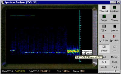 |
5B4/RW9UP working a CW pile up on 20 CW. On the left side of the display a station is signing with RW9UP. In the center of the display, RW9UP is sending QSL info, then standing by. A number of stations then start calling. |
By watching for patterns in a DX station's operating habits you can significantly increase your chances of working him/her. A DX operator may arbitrarily work through a pile up from low frequency to high, tuning his receiver higher in frequency after each contact. It is more common for a DX operator to respond to stations close to the frequency of the last contact. In either case, the CommCat Spectrum Analyzer can help.
The Spectrum Analyzer provides up to a 2.7 kHz frequency/time view of the pile up. By listening to the radio audio and watching the spectrum, you will quickly learn how to spot a station that is in contact with the DX station. For this to be true, a propagation path to the station working the DX station must exist, and the pass band of your receiver must be wide enough to allow the full spectrum analyzer bandwidth to be used. When you identify the station working the DX station, simply click the associated spectrum analyzer trace, and your radio is tuned to the correct frequency. If you have identified a tuning pattern being used by the DX operator, click higher or lower in frequency as determined by your prediction of frequency step size.
The tuning procedure you use depends on the frequency difference between the pile up and the DX station, and the way your radio transmits CW. Yaesu radios typically use USB (Upper Sideband) in the CW mode, while other radios, such as Icom, use LSB (Lower Sideband). With USB radios you will see the DX station and an associated pile up on the same view, so long as the pile up is higher in frequency than the DX station, and is within 1-2 kHz. With LSB radios, it is not possible to see the DX station and pile up at the same time unless a "down" split is being used by the DX operator. For radios that use LSB on CW it may be possible to use CW Reverse for best use of the Spectrum Analyzer. The Elecraft K2 uses USB on the high bands and LSB on the low bands. Using the Advanced Settings for the Elecraft radio you can have CommCat automatically use CW-R on the low bands to provide USB on all bands.
The Spectrum Analyzer can be used in concert with the DX Tracker window. Double-click a frequency in the pile up to tune the radio to that frequency and set a tuning mark on the DX Tracker window. As you double-click on the stations that successfully contact the DX station, it is easy to see a developing pattern on the DX Tracker display.
Trouble Shooting
Here are some guidelines to determine why the Spectrum Analyzer is not working:
1. The Spectrum Analyzer computes the spectrum in your computer using a sound card supplied by audio from your radio.
2. Use the Line Input on the sound card. This connection requires a stereo plug. Connect the radio audio to the tip and ground to the sleeve. If your radio has two audio channels (for two receivers) connect the second audio output to the ring on the connector.
3. The line input to the sound card recorder must be enabled. You can check this on the Windows mixer panel.
4. When set up properly, you will be able to hear the radio audio through your computer speakers. If you don't hear the audio, the Spectrum Analyzer will not receive the proper signals.
5. You can adjust the Windows mixer audio level to lower or raise the level fed to the Spectrum Analyzer. You can also use the audio level slider on the Spectrum Analyzer to adjust the levels.
6. If your computer has multiple sound cards, you can select the correct source in File, Settings, Program, Spectrum Analyzer.